MSR Form explanation to the column: Current Diagnostic Monitoring
Contents:
1. General
2. Using the MSR Form on an existing FMEA with structure and nets
2.1 Data flow from existing FMEA (here failure net) into the MSR Form
2.2 Explanation of this data flow from an existing FMEA to the MSR Form
3. MSR Form: entering data directly
3.1 Data flow from MSR form into an automatically created system structure
3.2 Explanation of data flow from MSR Form to the automatically created system structure
1. General
The AIAG/VDA Form (MSR) – or simply MSR Form – is drafted in the new alignment of 2019. It is divided into the two sections “Risk Analysis (step 5)” i.e. representation of the actual status of the FMEA and “Optimization (step 6)” i.e. representation of the planned FMEA status. The AIAG/VDA 2019 manual uses the example of a Window Lift System to demonstrate FMEA-MSR and APIS has used the same example to explain certain aspects here when using the IQ-Software. Furthermore, an .fme file has been programmed. For the sake of clarity, only the structure from the manual with a hybrid net is used. This file can be downloaded here.
2. Using the MSR Form on an existing FMEA with structure and nets
2.1 Data flow from existing FMEA (here failure net) into the MSR Form
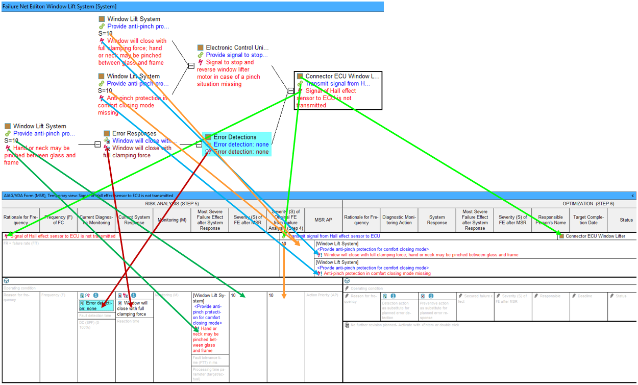
The following image gives a general overview of how data flows from the failure net into the MSR Form. As the cell for “Current Diagnostic Monitoring” is selected, it is highlighted in turquoise. This applies to the same element displayed in the failure net from which the data originates.
2.2 Explanation of this data flow from an existing FMEA to the MSR Form
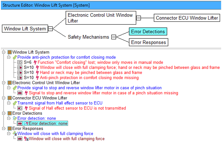
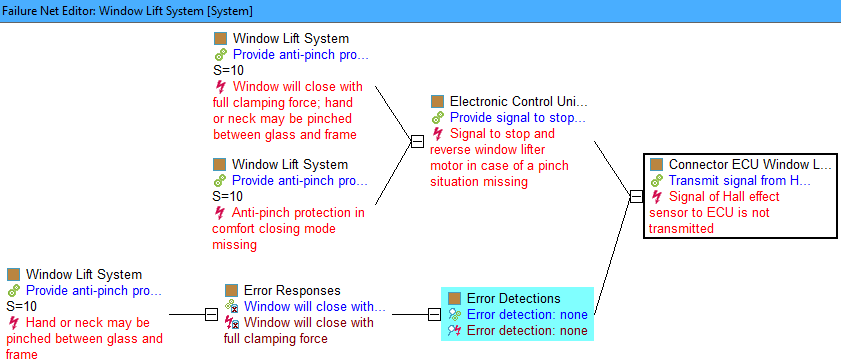
The safety mechanism type: “Error detection” is entered for the selected cell “Current Diagnostic Monitoring” in the MSR form. If an FMEA with error detections linked in the failure net already exists, these error detections can be found here as well, as shown in the following image. (To achieve the same display as the image, remove “actions” in the display options of the Structure Editor and Failure Net Editor).
If, for example, the structure element (SE) “Connector ECU Window Lifter” is synchronized with the MSR form from the Structure Editor, the synchronized SE including its function and corresponding failure is listed in the first line of the upper MSR form area. The row below this contains all top failures connected to the failure with the highest S ratings (for this failure). These top failures are also referred to as unsecured failure effects. If the synchronized SE has multiple functions/failures, this upper MSR form area is created as often as there are anchored failures in that synchronized SE.
In this example, using the AIAG/VDA Window lift system, the failure “Signal of Hall effect sensor to ECU is not transmitted” has two unsecured failure effects: “Window will close with full clamping force; hand or neck may be pinched between glass and frame” and “Anti-pinch protection in comfort closing mode missing”.
Because both top failures are rated S=10, they are listed in the upper part of the MSR form. If the S ratings are missing, the field for secured failure effect(s) remains empty.
In the lower section of the MSR Form, a number of columns are reserved for the risk analysis (step 5) as well as
for optimization (step 6), depending on how you select your display options. Above the selected cell “Current
Diagnostic Monitoring“, you can see the icons  ,
, ![]() or
or
![]() .
The icon
.
The icon  opens up a help page for MSR forms (using right-click). For an
empty cell, the icon
 ![]() indicates that an
error detection is needed there. For a
filled cell, the icon
indicates that an
error detection is needed there. For a
filled cell, the icon ![]() indicates that an
error detection exists here that also
exists and is linked in a failure net but is not linked to a detection action in the action group “Customer
operation“. However, these links are absolutely necessary for these error detections to appear in the
correct place in the MSR form. In the example, this applies to the current error detection (step 5) “Error
detection: none” and the error detection still to be implemented (step 6) “Plausibility check between motor
current and Hall effect sensor”.
indicates that an
error detection exists here that also
exists and is linked in a failure net but is not linked to a detection action in the action group “Customer
operation“. However, these links are absolutely necessary for these error detections to appear in the
correct place in the MSR form. In the example, this applies to the current error detection (step 5) “Error
detection: none” and the error detection still to be implemented (step 6) “Plausibility check between motor
current and Hall effect sensor”.
If you do see the icon ![]() in the cell
“Current Diagnostic
Monitoring” but not the
in the cell
“Current Diagnostic
Monitoring” but not the  icon, please use the context menu on
the error detection in the MSR Form and select the option “Derive actions for customer operation” to create a link
to a detection action created during this process. If this is done correctly, the following icon will appear in
the selected cell:
 ![]() . At the same time,
and
the failure net link is
responsible for this, an initial state is created for the direct cause of the error detection, namely “Signal
of Hall effect sensor to ECU is not transmitted”. This has the action group “Customer operation”
which contains the newly created detection action.
. At the same time,
and
the failure net link is
responsible for this, an initial state is created for the direct cause of the error detection, namely “Signal
of Hall effect sensor to ECU is not transmitted”. This has the action group “Customer operation”
which contains the newly created detection action.
The same principle applied to error detections should also be applied to error responses in the MSR form. As such, error responses should be linked to preventive actions in Customer operations (if they do not yet exist).
The following are snippets from the Structure Editor and the MSR Form. 
In some cases, you may see the following icon also appear in the cell:![]() . This indicates a special
situation, which is not obvious when simply viewing the MSR Form, whereby the IQ-Software has recognised a certain
data constellation in the document. Right-click on the icon
. This indicates a special
situation, which is not obvious when simply viewing the MSR Form, whereby the IQ-Software has recognised a certain
data constellation in the document. Right-click on the icon![]() to
learn more about the case.
to
learn more about the case.
In the Window Lift System .fme example (download link at top of page), both safety mechanisms are linked to corresponding actions in customer operation. These are “Error detection: none” and “Window will close with full clamping force“. To see this, make sure that “actions” is ticked in the display options for the Structure Editor and Failure Net Editor.
Finally, on the subject of “Data flow from existing FMEA into the MSR Form”, the following can be derived from the failure “Signal of Hall effect sensor to ECU is not transmitted” (listed in the upper section of the MSR form and from the failure net): The failure effect “Hand or neck may be pinched between glass and frame” occurs after the error response “Window will close with full clamping force” in the so-called secured failure path (which in our example is actually not secured at all, because there is only the error detection “Error detection: none“). The MSR Form has the column “Most Severe Failure Effect after System Response” for this purpose. If there are multiple failures (on the same level) with maximum S ratings, these will also be displayed in this column. This column stays empty if the failures have no S ratings assigned.
3. MSR Form: entering data directly
3.1 Data flow from MSR form into an automatically-created system structure
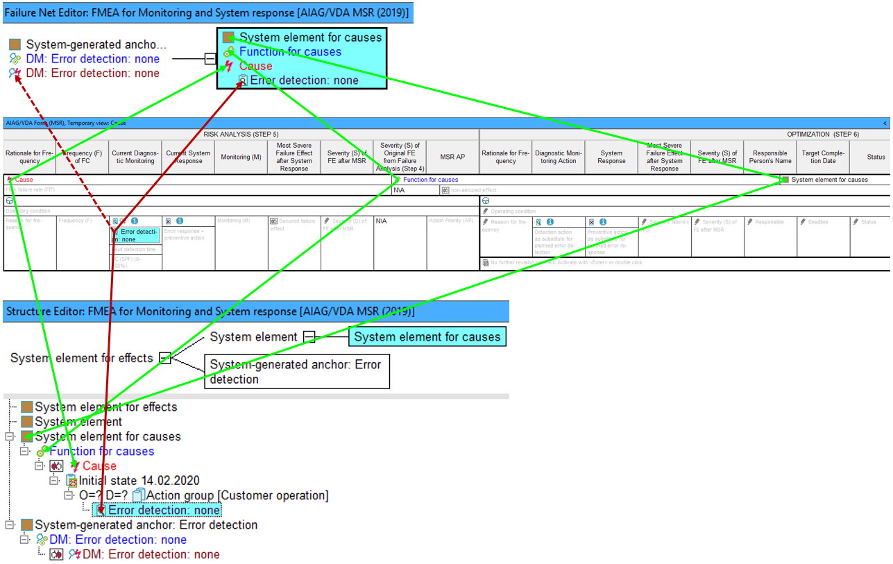
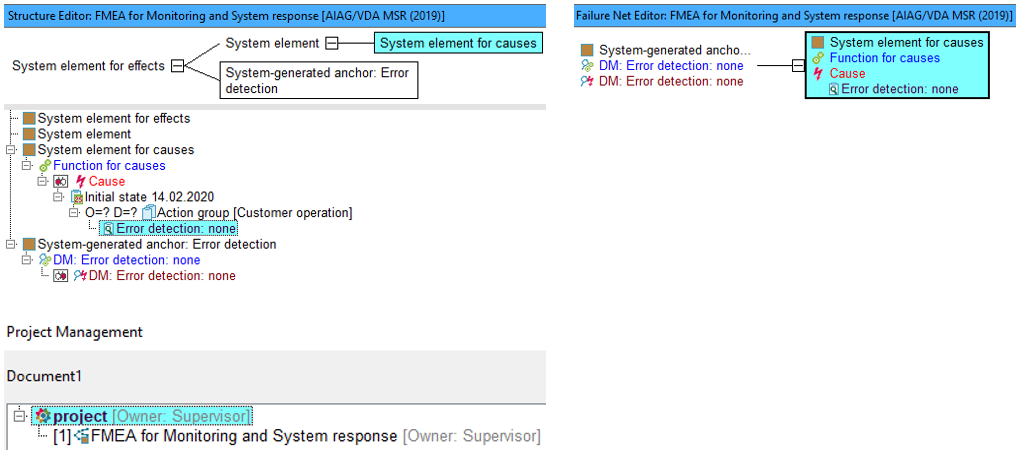
The following image gives an overview of how the data flows from the (initially empty) MSR form into an FMEA that is yet to be created (using the IQ-Software). The same example here is used (Window Lift System). The turquoise cell highlighted is “Current Diagnostic Monitoring” and its element will be the first entry in the FMEA. It must be an error detection and in the image below you can see the synchronised element in both the Structure Editor list and the failure net (automatically created by the IQ-Software). Why this is the case and why more IQ-Objects appear in the MSR Form than you have entered at this point is explained in detail in Chapter 3.2 below.
3.2 Explanation of data flow from MSR Form to the automatically created system structure
Using the example from Window Lift System, the safety mechanism to be entered into the cell “Current
Diagnostic Monitoring” is “Error detection: none”. Once this object is entered, the MSR Form
looks as follows:
As can be seen, not only has an error detection been created in the “Current Diagnostic Monitoring” cell, but also a failure “Cause“, a function “Function for causes” and a structure element “System element for causes” in the MSR form. This is more clearly viewed by switching to the Structure Editor as is shown in the following image. The header (in blue) also indicates that an FMEA for Monitoring and System response has been generated. This project is located under “project“, which can be checked in Project management (Menu | Administration | Project management).
APIS IQ-Software works with .fme file types. As this new document is generated by the IQ-Software, so is an automatically named .fme file as well. In this example, the new document is named “Document 1“. This filename can be changed by the user at any time. The same principle applies to objects automatically generated by the IQ-Software. They are automatically assigned a generic name, but this can be changed by the IQ-user.
The reason that several IQ-objects are created upon entering a new error detection in the (previously empty) MSR Form, is that elements are linked to each other within the IQ-Software. When entering a new error detection, the IQ-Software creates a new structure of IQ-elements that are linked. This is easier to see in the Structure Editor or Failure Net Editor.
In the case of directly entering an error detection, it is important to note that actions in customer operation can be derived from safety mechanisms. This is explained in 2.2. Here, detection actions are created from error detections and preventive actions are created from error responses. These derived actions must be anchored to a failure cause, which can be better controlled by safety mechanisms (in terms of failure effects). Furthermore, IQ-objects are anchored in a particular way to each other; actions are anchored to failures, failures to functions, and functions to structure elements. When directly entering an error detection, these elements do not already need to exist within the file as IQ-objects, as they can be entered directly into the MSR Form as well.
When an error detection is entered into the empty cell “Current Diagnostic Monitoring“, the IQ-Software automatically creates a detection action with the same name. This action is stored in the action group “Customer operation” (which also gets created). In the Window Lift System example, the detection action “Error detection: none” gets added to the action group “Customer operation” of the failure “Cause“.
The newly created detection action is now anchored in the way depicted in the image above because the failure “Cause” is immediately followed in the failure net by the error detection “Error detection: none”. In other words, the error detection secures the failure.
Another way to notice that the IQ-Software is deriving data once an error detection is entered (directly into the
MSR Form), is the appearance of the two icons ![]() and
and ![]() directly above the cell. However, there may be “indirect” entries in the cell for error detections for which no
corresponding detection actions (of group “Customer operation“) exist. In this case the icon
directly above the cell. However, there may be “indirect” entries in the cell for error detections for which no
corresponding detection actions (of group “Customer operation“) exist. In this case the icon ![]() will not appear. See section 2.2 for more information on this case, as it is recommended to use the context menu
command “Derive actions for customer operation” to create the detection action. The same IQ logic applies here,
whereby the detection action is assigned the same name as the error detection and if the action group “Customer
operation” does not exist, it will be created.
will not appear. See section 2.2 for more information on this case, as it is recommended to use the context menu
command “Derive actions for customer operation” to create the detection action. The same IQ logic applies here,
whereby the detection action is assigned the same name as the error detection and if the action group “Customer
operation” does not exist, it will be created.
With the information provided here, the image above (Structure Editor) should be almost self-explanatory. It should be noted though, that the automatically created structure is limited to three levels for reasons of clarity. In the case of the Failure Net Editor, it should also be clear now, why the IQ-Software creates certain linked elements when an error detection is entered directly into the MSR Form.
The automatically created structure can be used when further expanding your FMEA using the IQ-Software. Multiple editors are available to you to view and edit your data in various ways. You can also work directly with the MSR Form. Note here that by entering data here in other columns, further automatic creations of elements may occur.
